Discover Easy, Affordable, and Reliable PCB manufacturing with JLCPCB! Register to get $60 New customer coupons: Special Deal: Get a $30 coupon for JLCPCB premium 6-layer PCBs: 00:00 Introduction 00:53 Disclaimer 01:08 The Parts 02:37 Removing the cells 06:28 Preparing the cells 08:04 Combining the cells together 10:06 Ordering the PCBs 10:33 Balance charging the cells 12:42 Modifying & installing PCBs 13:23 Wiring up the USB board 15:07 Testing the Powerbank The open source repository (PCB files, 3D prints, Parts etc.): NOTE: The following links are affiliate links Parts used in this video: - USB Board (Type 1) - recommended Exact board used in this video Make sure to select the 5S version! - USB Board (Type 2) Has an extra type C port, but requires a different 3D printed enclosure (see the repository) Make sure to select the 5S version! - JST connector + wires Make sure to select , Length 10CM, 4P - Conductive copper tape Make sure to select '10mm' and 'Conductive on both sides' - Cell Tester - Programmable Load - Soldering iron (TS80p) 3D prints: - Files used in this video (for 13400 cells) - For other sized 13mm cells @montecha_2397581/collections/2035794 Selecting the resistor to set the power bank capacity: NOTE: This may differ depending on your board, double check the datasheet. - Calculate the capacity for a single row - Find the cell capacity in mAh (should be written on the cell). E.g. 550 mAh - Multiply it by 7 to get the whole row capacity. E.g. 7 * 550 = 3850 - Multiply the capacity by 0.8. E.g. 3850 * 0.8 = 3080 - Find an 0603 sized resistor with the closest resistance to the above number . E.g. 3000 ohms - Remove resistor R8 from the back of the USB board - Solder the new resistor on to R8
- 351502Просмотров
- 10 месяцев назадОпубликованоChris Doel
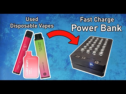
Making a Power Bank from Disposable Vapes: UPGRADED + Extreme Tests!
Похожее видео


Популярное
Новини