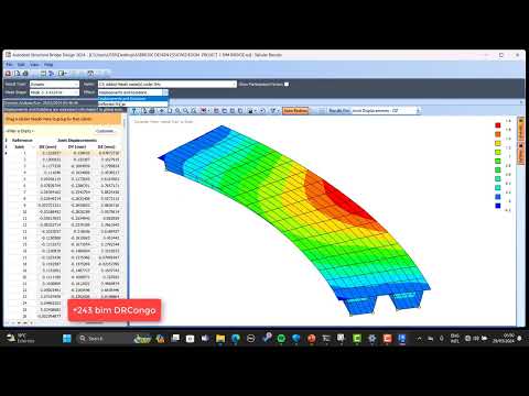
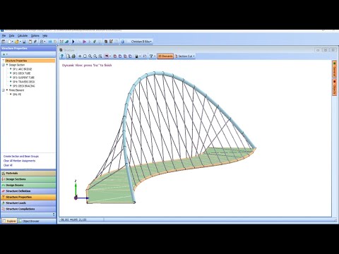
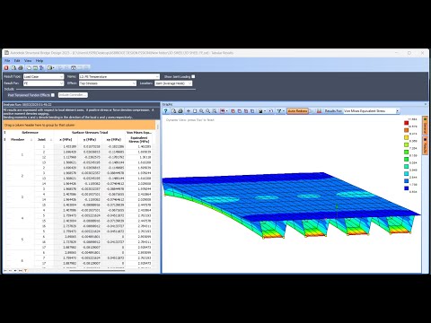
A cable-stayed bridge has one or more towers (or pylons), from which cables support the bridge deck. A distinctive feature are the cables or stays, which run directly from the tower to the deck, normally forming a fan-like pattern or a series of parallel lines. This is in contrast to the modern suspension bridge, where the cables supporting the deck are suspended vertically from the main cable, anchored at both ends of the bridge and running between the towers. The cable-stayed bridge is optimal for spans longer than cantilever bridges and shorter than suspension bridges. This is the range within which cantilever bridges would rapidly grow heavier, and suspension bridge cabling would be more costly. Comparison with suspension bridge In cable-stayed bridges, the towers are the primary load-bearing structures that transmit the bridge loads to the ground. A cantilever approach is often used to support the bridge deck near the towers, but lengths further from them are supported by cables running directly to the towers. That has the disadvantage, unlike for the suspension bridge, that the cables pull to the sides as opposed to directly up, which requires the bridge deck to be stronger to resist the resulting horizontal compression loads, but it has the advantage of not requiring firm anchorages to resist the horizontal pull of the main cables of the suspension bridge. By design, all static horizontal forces of the cable-stayed bridge are balanced so that the supporting towers do not tend to tilt or slide and so must only resist horizontal forces from the live loads. in this tutorial video we are juste showcasing the process of modeling of cable-stayed bridge in using AutoCAD and Autodesk structural bridge contact me on LinkedIn for more update of features contents our facebook page
- 758Просмотров
- 10 месяцев назадОпубликованоBIM DRCONGO
Cable-Stayed Bridge modeled in Autodesk structural bridge design
Похожее видео


Популярное
Новини