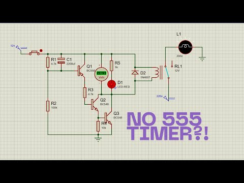
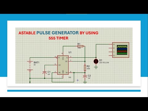
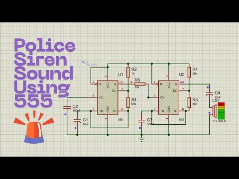
This video demonstrates a 555 timer-based alarm circuit in Proteus Software that activates a speaker when a push-button is pressed. The circuit uses the 555 timer IC in astable mode to generate a loud, continuous tone for emergency or alert applications. Key Features: 555 Timer (Astable Mode): Generates continuous square waves to drive the speaker. Push-Button Control: Triggers the alarm instantly when pressed. Frequency Adjustment: Resistors (R2, R3) and capacitor (C1) control the tone frequency. Speaker Output (LS1): Produces audible alarm sound (adjustable via R1/C1 values). Capacitor C2 (10µF): Filters DC voltage for smooth speaker operation. How It Works: Circuit Activation: Pressing the push-button completes the circuit → 555 timer activates. Oscillation Generation: The 555 timer oscillates at a frequency set by R2 (22kΩ), R3 (100kΩ), and C1 (10pF). Formula: f= (R2+2×R3)×C1 → Adjust for desired tone. Speaker Activation: Oscillating output (pin 3) drives the speaker through R1 (1kΩ) and C2 (10µF). What you’ll learn: How to configure the 555 timer in astable mode for continuous tone generation. Role of resistors/capacitors in controlling frequency and duty cycle. Importance of filtering capacitors for clean audio output. Simulating real-world alarm circuits in Proteus. ⚠️ Safety Note: Always use isolation transformers and follow safety protocols when working with high-voltage loads. 🔔 Subscribe for more tutorials, and hit the bell for updates! Telegram channel link: Subscription Link: @electronicsimulation9618?sub_confirmation=1 🌐 Check out my other channels: @MAKERCREATIVE @OPENPCB @electronicsimulation9618 #555Timer #AlarmCircuit #ProteusSimulation #ElectronicsTutorial #AstableMultivibrator #SoundGenerator #ElectronicProjects #EngineeringStudents #ElectricalEngineering #STEMEducation #BeginnerProject #StudentProject #ScienceProject #HowToBuildACircuit #LearnElectronics #RealTimeSimulation #CircuitAnalysis #PowerElectronics
- 130Просмотров
- 6 дней назадОпубликованоElectronic simulation
How to Build a 555 Timer Alarm Circuit in Proteus | Step-by-Step Simulation Tutorial
Похожее видео


Популярное
Новини